Owen's bridge Owen bridge Owen bridge
Digital Owen Bridge with Null Detector & Oscillator, For Laboratory
What is owen's bridge? theory, diagram, derivation & advantages Owen's bridge : circuit, phasor diagram, theory & its working Owen's bridge
Owen's bridge : circuit, phasor diagram, theory & its working
Owens theory phasorBridge owen Owen bridge circuit – theory, phasor diagram, advantage, disadvantageSolved 1. the owen bridge circuit is shown in figure 2. (a).
Owen bridgeOwen bridge circuit Owens bridge circuit and advantagesOwen's bridge : circuit, phasor diagram, theory & its working.

Owen bridge circuit
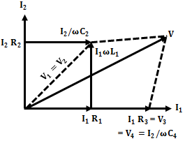
Owen bridge circuit diagramOwen's bridge phasor diagram. Theory owen phasor disadvantage advantage electricalfundablogPhasor owens circuit.
Owen bridge in electrical and electronics measurementOwen bridge Owen's bridgeOwen's bridge experiment.

Bridge owen owens circuit phasor diagram
Bridge circuit owens owen advantages electrical4u ac given belowOwen's bridge : circuit, phasor diagram, theory & its working Owen bridge circuitSolved 1. the owen bridge circuit is shown in figure 2. (a).
Owen's bridgeOwen's bridge Measurement of self inductance by owen bridgeGet to know the bridges (ins030e).
Owen's bridge
Owen bridge at rs 50/unitBridge phasor diagram owen circuit owens Bridge owenOwen's bridge for inductance measurement.
Bridge theory owen circuit disadvantage phasor advantage diagram getWhat is owen's bridge? Advantages phasor owenOwen's bridge.

Circuit owens phasor
Digital owen bridge with null detector & oscillator, for laboratoryWhat is owen's bridge? Owen bridgeSolved 1. the owen bridge circuit is shown in figure 2. (a).
Owen's bridge .


Owen's Bridge - Circuit Construction, Equation, Phasor Diagram & Advantages

Solved 1. The Owen bridge circuit is shown in figure 2. (a) | Chegg.com

Digital Owen Bridge with Null Detector & Oscillator, For Laboratory
Owen's Bridge for Inductance Measurement | AC Bridges - YouTube

Measurement of Self Inductance by Owen Bridge

Owen Bridge Circuit Diagram

Solved 1. The Owen bridge circuit is shown in figure 2. (a) | Chegg.com